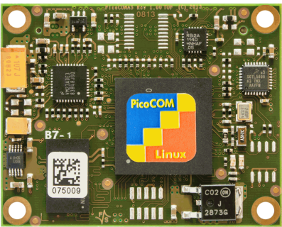
PicoCOM
PicoCOM – A Future-Proof Embedded Platform
The PicoCOM module family has been a proven foundation for compact embedded systems for many years. The hardware itself will remain available for many years to come. Many existing designs still rely on Microsoft Windows Embedded Compact 2013, which will be discontinued in 2028 and no longer receives security updates.
With the upcoming Cyber Resilience Act (CRA) becoming mandatory by the end of 2027, requirements for security, update capability, and software transparency are increasing significantly. Manufacturers must ensure that their products remain secure, maintainable, and traceable throughout their entire lifecycle.
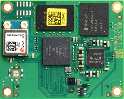
The Next Step: PicoCOM93 with NXP i.MX 93
The new PicoCOM93 has been specifically designed to support this transition.
It is based on the modern NXP i.MX93 processor and provides a Linux-based platform with integrated security features and long-term availability. Key features:
- Security by Design: Hardware-based security through the integrated EdgeLock Secure Enclave, enabling secure boot, key management, and hardware root of trust in line with CRA requirements.
- Reliable Update Strategy: Generous eMMC storage supports A/B update and over-the-air (OTA) updates for secure and reliable system updates.
- Transparent Software Architecture: Based on Linux Yocto, enabling reproducible builds, SBOM (Software Bill of Materials) generation, and long-term maintainability.
- Connectivity: Also available with Wi-Fi 6 and Bluetooth, making it ideal for modern industrial and IoT applications.
- Long-Term Availability: Industrial-grade design with components covered by the NXP Longevity Program, ensuring availability for up to 15 years. This makes the PicoCOM93 a reliable platform for long-life industrial products.
With the PicoCOM93, developers gain a powerful, energy-efficient, and future-proof embedded platform to migrate from Windows CE to Linux — fully aligned with the upcoming requirements of the Cyber Resilience Act.
| PicoCOM1 | PicoCOM1.2 | PicoCOMA5 | PicoCOMA9X | PicoCOMA7 | PicoCOM93 | |
| State | No New Developments | Production | Production | Production | Production | Samples |
| CPU | - | - | - | - | - | - |
| CPU | ATMEL | NXP i.MX 6UL | NXP Vybrid | NXP i.MX 6SoloX | NXP i.MX 6ULL | NXP i.MX 93 |
| Core | ARM 926 EJ | ARM Cortex-A7 | ARM Cortex-A5 + Cortex-M4 | ARM Cortex-A9 Cortex-M4 |
ARM Cortex-A7 | ARM Cortex-A55 Cortex-M33 NPU |
| No of Cores | - | 1 | Single-/Dual-Core | 1x A9 + M4 | 1 | 2x A55 + M33 + NPU |
| Frequency | 210 MHz | max. 900MHz | max. 500MHz + 167 MHz | max. 1GHz + 200 MHz | max. 900MHz | 1.7GHz + 250MHz |
| L2-Cache | - | 128KB | 512KB | 256KB | 128KB | 2x64kB L2 + 256kB L3 |
| NPU | - | - | - | - | - | 0.5 TOPS |
| GPU | - | - | - | 2D, 3D | - | PXP |
| Security | - | - | - | - | - | - |
| Secure Element | - | - | - | - | - | SE050 Edgelock Secure Enclave |
| Operating System | - | - | - | - | - | - |
| Linux | 2.6 (Emlix Eval/ Pro) (uboot installed) |
Buildroot/Yocto (uboot installed) |
Buildroot (uboot installiert) |
Buildroot Yocto (uboot installed) |
Buildroot Yocto (uboot installed) |
Yocto (uboot installed) |
| Windows | CE/Compact (EBoot installed) |
CE/Compact (EBoot installed) |
CE/Compact (EBoot installed) |
CE/Compact (EBoot installed) |
CE/Compact (EBoot installed) |
11 IoT Enterprise (UEFI installed) |
| Real Time | - | - | - | FreeRTOS | - | FreeRTOS |
| Memory | - | - | - | - | - | - |
| Flash | 512MB SLC NAND | 512MB SLC NAND | 512MB SLC NAND | 512MB SLC NAND | max. 512MB SLC NAND | 64kbit EEPROM |
| eMMC | - | - | - | - | - | max. 64GB |
| RAM | 32MB+ | max. 512MB | max. 512MB | max. 512MB DDR3L x16 | max. 1GB DDR3L x16 | max. 2GB LPDDR4 x16 |
| Interfaces | - | - | - | - | - | - |
| SD-Card | extern | 1x extern | 1x extern | 1x SDIO | 1x SDIO | 1x SDIO |
| Ethernet | 1x 100Mbit Phy | 10/100Mb | 1x/2x 100Mbit Phy | 1x/2x 100Mbit Phy | 1x/2x 100Mbit Phy | 1x/2x 100Mbit Phy |
| WiFi | - | - | - | - | - | WIFI 6 (2.4/ 5GHz) |
| BT | - | - | - | - | - | 5.4 |
| USB Host | 1-2 (2.0 FS) | 1x | 1-2x | 1x | 1x | 1x 2.0 |
| USB Device | 0-1 (2.0 FS) | 1x | 1x | 1x | 1x | 1x OTG 2.0 |
| CAN | 1 | 2x | 1-2x | 1-2x | 1-2x | 2x CAN-FD |
| UART | 1x mit Modemsignalen, Baudrate 115200 1x mit RTS/ CTS, max. Baudrate 115200 1x mit max. Baudrate 115200 |
6x | 3x | 2-3x | 3x | 3x |
| I2C | 1 | 2x | 1-2x | 1x | 1-2x | 2x |
| SPI | opt. | 2x | 1x | 1x | 1x | 1x |
| Audio | 1x Audio Codec Line Out (L/ R) 1x Audio Codec Line In (L/ R) 3x Analog In (10Bit resolution) |
Line In/Out/analog | Line In/Out | Line In/Out | Line In/Out | Line In/Out opt. I2S |
| Digital I/O | - | - | - | max. 48 | max. 48 | |
| ADC | - | - | - | - | - | 4x |
| Touch Panel | - | - | 4-wire, analog resistive PCAP-Touch via I2C |
4-wire, analog resistive PCAP-Touch via I2C |
4-wire, analog resistiver PCAP-Touch über I2C | TSC2004 |
| RTC | - | - | - | - | PCA8565 | PCF85263ATL |
| More | - | - | 2x 12Bit ADC | - | - | - |
| Display | - | - | - | - | - | - |
| RGB | - | - | 16/18bit | 16/18bit | 16/18 Bit | 18 Bit |
| LVDS | - | - | extern | - | external | - |
| Common | - | - | - | - | - | - |
| V_IN | +3,3V | +3,3V DC/ ±5% | +3,3V DC/ ±5% | +3,3V DC/ ±5% | +3,3V DC/ ±5% | +3,3V DC/ ±5% |
| T_AMB | -20°C - +85°C | 0°C - +70°C -25°C - +85°C |
0°C - +70°C -20°C - +85°C |
0°C - +70°C -40°C - +85°C |
0°C - +70°C -25°C - +85°C |
0°C - +70°C -25°C - +85°C -40°C - +85°C |
| Size | 40x50mm | 40x50mm | 40x50mm | 40x50mm | 40x50mm | 40x50mm |
| Availability | - | 2035+ Windows: May, 2028 |
2027+ Windows: May, 2028 |
2035+ Windows: May, 2028 |
2035+ Windows: May, 2028 |
2038+ |
| PicoCOM1 | PicoCOM1.2 | PicoCOMA5 | PicoCOMA9X | PicoCOMA7 | PicoCOM93 |

